Speaker Protection
![]()
Protects Your Precious Speakers
ALTHOUGH DESIGNED specifically for our Class-A Stereo Amplifer, this unit can actually be used with any audio amplifer with supply rails up to about 70V DC, simply by selecting two resistor values to suit.
Basically, the unit provides the following features:
- It protects the loudspeakers against catastrophic failure in the amplifier – eg, if an output transistor goes short circuit
- It provides muting at switch-on and switch-off, to prevent thumps from the loudspeakers
- It provides an input for an over-temperature switch to disconnect the loudspeakers if the output stage heat-sink temperature rises above a certain level.
Note, however, that this last feature is not used in the Class-A Stereo Amplifier. This is because its heatsinks run hot all the time (about 30°C above ambient) and disconnecting the loudspeakers does nothing to cool them down,
since the output stage in each amplifier module draws a constant 1.12A – equivalent to a power dissipation of just under 50W.
By contrast, disconnecting the loudspeaker from a class-B amplifier will immediately reduces the current through the output stage to the quiescent current setting – typically around 50mA (assuming that there’s no fault in the amplifier).
So, for a class-B amplifier, it makes sense to use over-temperature sensing. If the heatsink to which the output transistors are attached gets too hot, disconnecting the loudspeakers immediately reduces the dissipation to just a few watts, which allows the heatsink to cool.
Note that the loudspeakers are connected (and disconnected) using a heavy-duty double-pole relay. We’ll have more to say about that later.
Protecting the loudspeakers
By far the biggest reason for incorporating speaker protection into an amplifier is to prevent further damage in the case of a serious amplifier fault. For example, if the main supply rails are ±70V DC. This means that if one of the output transistors fails and there’s no loudspeaker
protection, more than 70V DC would be applied to the speaker’s voice coil.
In a nominal 8Ω speaker, the voice coil has a DC resistance of around 6Ω and so the power dissipation would be around 800W, until the supply fuse blew. In the meantime, this amount of applied DC power is likely to push the voice coil out of its gap, damaging the voice coil and suspension in the process.
And if the on-board supply fuse didn’t blow fairly quickly, the voice coil would quickly become red-hot and could set fire to the speaker cone material.
This risk applies to any audio power amplifier of more than about 40W per channel. So a loudspeaker protection circuit is a very good idea.
The risk of setting fire to the loudspeaker is nowhere near as great with the Class-A Stereo Amplifier because the supply rails are just ±22V. In this case, a shorted output transistor would result in a dissipation of about 80W in the speaker’s voice coil. It might not be enough to cause a fire, but it’s certainly
high enough to damage the loudspeaker by burning out the voice coil.
Muting the thumps
Muting switch-on and switch-off thumps is another important function of this unit.
Switch-on thumps are eliminated by using a simple circuit to delay the relay from turning on when power is first applied. This way, the amplifier modules are able to power up and settle down before the relay switches on (after about five seconds) to connect the speakers.
By contrast, switch-off thumps are eliminated by using an ‘AC Sense’ input to monitor the secondary AC voltage from the transformer (up to 50V AC max). When this AC voltage disappears (ie, at switch-off), the circuit switches the relay off in less than 100ms.
This is much faster than simply relying on the collapsing DC supply rail to turn the relay off. In practice, this could take half a second or more, as the main filter capacitors discharge – more than long enough for a any switch-off thumps to be audible.
Circuit details
Refer now to Fig.1 for the full Speaker Protection and Muting Module circuit details. As shown, each channel of the amplifier is connected to the NC and NO (normally closed and normally open) contacts of a relay. The relay wipers (poles) and NC contacts then each respectively connect to the positive and negative loudspeaker terminals.
Each channel of the amplifier is monitored for DC faults by a triplet of transistors – Q5, Q6 and Q7 for the left channel and Q8, Q9 and Q10 for the right channel. We’ll describe the operation of the left channel only, as the circuit for the right channel is identical.
As shown, the active signal from the amplifier’s left channel is fed to a low-pass filter consisting of two (47kΩ and 390kΩ) resistor and one 47μF/50V bipolar (BP or NP) electrolytic capacitor. This network removes any audio frequencies and just leaves DC (if present under fault conditions) to be monitored by the three transistors - Q5, Q6 and Q7.
This is because we don’t want audio signals to trip the protection circuit.
The low-passfilter output is connected to the emitter of Q7 and to the base of Q6. Transistor Q7 monitors the amplfier output for negative DC signals, while Q6 monitors for positive DC signals.
In operation, transistor Q6 turns on if a DC signal of more than +0.6V is present on its base. Similarly, Q7 turns on if a DC signal of more than –0.6V is present on its emitter. This in turn pulls transistor Q5’s base low and so Q5 also turns on.
Normally, in the absence of amplifier faults, transistors Q5-Q7 are all off and Q3 is biased on via the 220kΩ resistor connected between its base and the positive supply rail (ignore Q1 and Q2 for the time being). As a result, Q3 pulls Q4’s base down (via resistor R9) to just over 15.6V, as set by diode D5 and Zener diode D6, and so Q4 and relay RLY1 are also on.
Now let’s consider what happens if an amplifier fault condition results in DC being present at its output. In this case, either Q5 or Q6 turns on and pulls Q3’s base low via a 100Ω resistor. When that happens, Q3, Q4 and the relay all immediately turn off, disconnecting the speakers.
Diode D7 protects Q4 by quenching any back-EMF spikes that are generated when the relay is switched off.
Transistors Q8, Q9 and Q10 monitor the right channel of the amplifier and they switch Q3, Q4 and the relay in exactly the same manner.
Relay specifications
The relay selected for the job is a 24V DPDT (double-pole, double-throw) type, with contacts rated at 16A. There are two reasons for this high contact rating. First, we want the contact resistance in the relay to be as low as possible so that it has negligible effect on the amplifier’s performance, as regards to distortion, damping factor and so on.
Second, the relay contacts have to pass and break the heavy DC current which would otherwise flow through the loudspeaker if a fault occurs in the amplifier. However, we don’t merely use the relay to disconnect the amplifier’s output from the speakers. If we simply did this, it’s possible that the contacts would just arc across and so the heavy DC current would continue to flow through the loudspeaker.
That might seem unlikely, but when you have a heavy DC current and a high DC voltage pushing it along, it can be quite hard to break the circuit. This problem is solved by shorting the moving (pole) relay contacts to the loudspeaker ground lines (via the otherwise unused NC contacts) when the relays turn off. This diverts the arc current to chassis and ensures that the fuses blow on the amplifier.
By the way, the relay specified in the parts list (Finder 62.22.9.024.0000) has an in-built green LED that lights when the relay turns on. It’s a nice feature that lets you quickly check the status of the relay during testing, but it is not really necessary.
Muting delay at switch-on
Muting at switch-on is achieved using a delay circuit. This consists of the 220kΩ resistor and the 47μF capacitor connected to Q3’s base, along with diode D5 and Zener diode D6.
When power is first applied, the 47μF capacitor is discharged and Q3’s base is held low. As a result, Q3, Q4 and the relay all remain off. The 47μF capacitor then charges via the 220kΩ resistor until, after about five seconds, it reaches 16.2V. This now forward biases Q3, which then turns on Q4 and the relay to connect the loudspeakers. This is more than sufficient time for the amplifier modules to settle down and achieve stable operating conditions.
Why 16.2V on Q3’s base? Well, that’s the sum of the voltages across D6, diode D5 and Q3’s base-emitter junction when the transistor is on.
Switch-off muting
Transistors Q1 and Q2, together with diodes D2 and D3, provide the switch-off muting function.
Diodes D2 and D3 rectify the AC voltage that’s fed to the AC Sense input (at connector AC INPUT) from a transformer secondary winding (up to 50V AC max). Provided this AC input voltage is present, the rectified output forward biases transistor Q1 and so keeps it turned on. This in turn holds Q2’s base low and so Q2 is off and Q3 functions normally.
The 100kΩ resistor and the 470nF capacitor, at Q2’s base, form a time constant that’s long enough to ensure the Q2 remains off when Q1 very briefly turns off during the AC zero crossing points.
However, if the AC signal ceases (ie, at switch off), Q1 immediately turns off and Q2 turns on and quickly discharges (within a millisecond or so) the 47μF timing capacitor via a 100Ω resistor. As a result, Q3, Q4 and the relay all turn off and the loudspeakers are disconnected, effectively eliminating any switch-off thumps.
Connector THERMAL-L and THERMAL-R is the temperature sensor input. It relies on the use of a normally-open (NO) thermal switch that’s normally bolted to the heatsink used for the amplifier’s output power transistors.
Basically, this input is wired in parallel with transistor Q5 (and Q8) and it controls transistor Q3 in exactly the same manner.
When the temperature reaches a preset level (set by the switch itself), the contacts inside the thermal switch close and pull Q3’s base low via the associated 100Ω resistor. As a result, Q3 turns off and this switches off Q4 and the relay.
When the heatsink subsequently cools down, the thermal cutout opens again and Q3, Q4 and the relay turn on again to reconnect the loudspeakers.
As previously stated, the over-temperature sense feature is not used with the Class-A Stereo Amplifier because the heatsinks run hot all the time and disconnecting the loudspeakers does nothing to cool them.
Power supply
Power for the Loudspeaker Protection circuit is derived from a suitable DC rail within the amplifier. This can range anywhere from about 20V DC up to 70V DC.
In the case of the Class-A Stereo Amplifier, we use the +22V and 0V rails from the power supply board. The ‘AC Sense’ signal is picked up directly from the AC terminals on the bridge rectifier.
Note that the values shown for R5 and R10,R11 on Figs 1 and 2 assume a 48V to 50V supply rail. If the available DC supply rail is higher or lower than this, then resistors R5 and R10,R11 must be changed accordingly to
ensure a delay of five seconds for Q3 (as set by R5) and to ensure that no more than about 24V DC is applied to the relay coil (R10 and R11). In the latter case, it’s just a matter of selecting R10 and R11 so that the relay current is about 54mA (assuming that the relay has a coil resistance of about 445Ω).
The resistor values to suit differing supply rails is calculated from the bottom calculator.
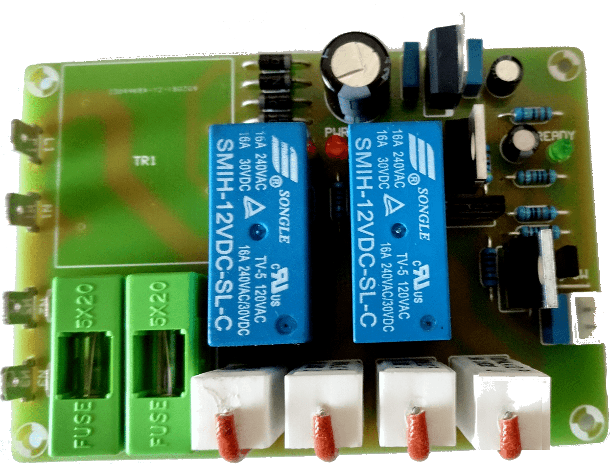
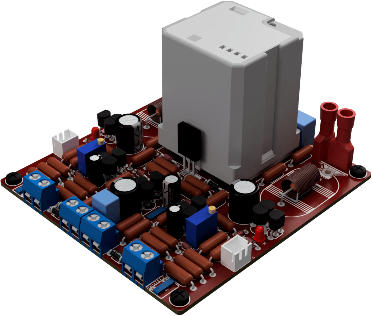
Fig.2: install the parts on the PC board as shown here, taking care
to ensure that all polarised parts are correctly oriented. Also, make certain you use the correct transistor type at each location. Below is the completed PC board.
OverCurrent / OverLoad Protection
Sensing resistors (LIN-TOP/BOT and RIN-TOP/BOT) monitors both half-cycles voltages on both output transistors (only one pair if there are more pairs in OPS).
Diode D14 and resistor R27 translates the negative half-cycle voltage, since the voltage across the emitter resistor is negative and we have a more symmetrical appearance at the collector of Q13.
The RC constant (4.7μF and 68kΩ) is present so as not to trigger the detection at each slightly larger current pulse at the output, but only after a certain repetition time of these larger pulses.
If the voltage at collector Q13 pulse series stops at that time, the detection returns to StandBY.
We maintain this StandBY state:
- set 10kΩ multiturn trimmer to 0Ω (short-circuit) so that it would take an enormous current to get voltage sense activated.
- load the amplifier output with nominal load - eq, 8R0
- place an oscilloscope at the output
- set DMM in mVDC mode on TestPoint points (Voltmeter must have input impedance 1M +)
- turn on the amplifier and the signal generator with sinewave 100Hz at the input of the amplifier
and raise the amplitude until the amplifier output starts slightly(SOFT) clipping
(per oscillogram on an oscilloscope - just a little to cut our amplitude peaks)
- now with the 10kΩ trimmpot adjust so that we read on the DMM around 400-420mV
Now if we raise the input amplitude on the amplifier to read on oscillogram HARD clipping, the DMM will show a higher voltage of about 450-600mV and this will activate BJT detection which is connected by an emitter to GND.
By activating the BJT, it will start discharging through its collector with 100Ω and 47μF capacitor and when that voltage on that capacitor drops below about 16.4V it will deactivate relay.
The 22nF capacitors are there due to possible interference, so that we don’t trigger our detection prematurely.
Construction
The parts for the Speaker Protection and Muting Module are all mounted on a PC board. This board is available in PDF files (see above). Fig.2 shows the component layout and assembly details.
Mount the jumpers, resistors and diodes first, taking care to ensure that the diodes are all oriented correctly. Table 1 shows the resistor colour codes, but you should also check each resistor using a digital multimeter before installing it, just to be sure.
Install a 100kΩ 0.25W resistor for R5 and a link for R10 and R11 if you are building the unit for the Stereo Class-A Amplifier.
Alternatively, select these resistors from the bottom calculator if you intend using a supply rail greater than 24V.
If the calculated resistor value is between the standard value, then simply scale the resistor values accordingly and use the nearest preferred value.
The six pcb solder fastcon connectors for the speaker input and output terminals are next on the list. These are soldered into a PCB and connected with female fastcon connector – see Fig.3.
The transistors, the electrolytic capacitor and the bipolar capacitors can now be installed, taking care to ensure that the correct transistor type is fitted to each location. The two 47μF bipolar capacitors can go in either way around, but do watch the orientation of the polarised 47μF/63V electrolytic capacitor.
Finally, you can complete the board assembly by fitting the four 2-way terminal blocks and the DPDT relay.
Testing
If you have a suitable DC supply you can test the unit prior to installing it. To do this, first connect the supply to screw terminal block DC INPUT and install a wire link between one of the AC INPUT ‘AC Sense’ input terminals and the positive supply rail (this is done to ensure transistor Q1 turns on). Do not connect anything to the
temperature switch input or to the speaker terminals at this stage.
Next, apply power and check that the relay turns on after about five seconds. If it does, temporarily short the temperature switch input – the relay should immediately switch off.
Similarly, the relay should immediately switch off if you disconnect the link to the AC Sense input.
The next step is to check that the relay switches off if a DC voltage is applied to the loudspeaker terminals (this simulates an amplifier fault condition). To do this, apply power, wait until the relay switches on, then connect a 3V (2 × 1.5V cells in series) or 9V battery (either way around) between the ground terminal of DC INPUT and the AMP-L terminal. The relay should immediately switch off.
Repeat this test for the AMP-R terminal, now reverse the battery polarity and perform the above two tests again. The relay should switch off each time the battery is connected.
Note that we don’t connect to the GND-L or GND-R terminal for this test because these two inputs are fully floating at this stage. That changes when the module is installed in a chassis and the loudspeaker leads are connected, because the negative loudspeaker terminals on the amplifier are connected to chassis (via the power supply).
Troubleshooting
If the relay doesn’t activate when power is first applied, switch off immediately and check for wiring errors – eg, incorrect supply polarity, or a transistor in the wrong location. If this doesn’t locate the fault, switch on and check the supply voltage, then check the voltages around the transistors. Q3’s emitter should be at about 15.6V and its collector at 15.8V, while both Q3 and Q4 should have base-emitter voltages of 0.6V.
Similarly, Q1 should have a base-emitter voltage of 0.6V (provided the link between the AC Sense input and the positive supply terminal is in place) but the other transistors (Q2 and Q5 to Q10) should all be off – ie, they should have base-emitter voltages of 0.2V or less.
If Q3’s base voltage is low (around 0.2V), then it could mean that Q2 is on and Q1 is off, possibly due to no voltage being applied to Q1’s base. Alternatively, one of the transistors in the speaker input monitoring circuits (ie, Q5 to Q10) could be faulty (short circuit). You can quickly isolate which circuit section is at fault by disconnecting the 100Ω resistor to Q3’s base.
Just remember that all transistors that are turned on will have a base-emitter voltage of about 0.6V. This should enable you to quickly locate where the trouble lies.
Bill of Materials
| Name | Value | Quantity |
|---|
| R1* | *Ω | 1 |
| R2 | 12kΩ | 1 |
| R3,R24,R28,R31,R35 | 100kΩ | 5 |
| R4 | 100Ω | 1 |
| R5* | *Ω | 1 |
| R6* | *Ω | 1 |
| R7* | *Ω | 1 |
| R23,R30 | 33kΩ | 2 |
| R8 | 10kΩ | 1 |
| R9* | *Ω | 1 |
| R10*,R11* | *Ω | 2 |
| R12*,R13* | *Ω | 2 |
| R14,R18 | 390kΩ | 2 |
| R15,R19 | 47kΩ | 2 |
| R16,R20 | 10Ω/2W | 2 |
| R17,R21 | 2Ω2/3W | 2 |
| R22,R29 | 3.3kΩ | 2 |
| R25,R32 | 56kΩ | 2 |
| R26,R33 | 68kΩ | 2 |
| R27,R34 | 330kΩ | 2 |
| LIN-TOP,RIN-TOP | *Ω | 2 |
| LIN-BOT,RIN-BOT | 330Ω | 2 |
| Q1,Q2,Q3,Q6,Q7,Q9 | 2N5551 | 6 |
| Q10,Q11,Q13,Q14,Q16 | 2N5551 | 5 |
| Q4 | MJE350 | 1 |
| Q5,Q8,Q12,Q15 | 2N5401 | 4 |
| D1,D2,D3,D7 | 1N4007 | 4 |
| D4,D5,D8,D9,D10 | 1N4148 | 5 |
| D11,D12,D13,D14,D15 | 1N4148 | 5 |
| D6 | 15V/1.3W | 1 |
| C1 | 100μF/100V | 1 |
| C2 | 470nF/63V/MKT | 1 |
| C3 | 47μF/63V | 1 |
| C4,C6 | 47μF/50V | 2 |
| C5,C7 | 100nF/100V/MKP | 2 |
| C8,C11 | 4.7μF/50V | 2 |
| C9,C10,C12,C13 | 22nF/63V | 4 |
| P1,P2 | 10kΩ | 2 |
| LED1,LED2 | RED 3mm | 2 |
| AMP-L,AMP-R,SPK-L | 1-726388-2 | 3 |
| SPK-R,GND-L,GND-R | 1-726388-2 | 3 |
| AC,DC | KF301-2P | 2 |
| THERMAL-L/R | JST-XH2.54-2 | 2 |
| RLY1 | 62.22.9.024.0000 | 1 |
| SCREW1-4 | M3 | 4 |
Download
- Speaker Protection - Schematic (PDF)0
- Speaker Protection - Layout (PDF)0
- Speaker Protection - PCB (PDF)0